
How to build your High Voltage power supply
1 - Introduction
They are many ways to produce the high voltage that is needed to study the corona glows and their E.H.D applications. The oldest one (but still an option not too bad) is the mechanical electrostatic machines (Wimshurst, Van de Graaff,....) in such machine the high voltage is produced by charges carried to the high voltage electrode by a solid mechanical stuff (a rotating disk, a belt,....). Such machines can produce very high voltages in a quite a simple manner, moreover they can be motorised. Their main limitation apart from their sizes is the very small current that they can deliver. By the way there is a chronic abuse of language here, normally the world static should be avoided here because not only there is a mechanical movement, but there is also an electrical current flowing through the machine (even very small), the proper name should rather be non neutral conduction machines, to state a clear difference with the usual electric conduction.
Apart from such machines, high voltage can also be produced by piezoelectric effect. Note that piezoelectric resonators can be mechanically activated but can also be operated purely electrically, like any other transformer. The main limitation of piezoelectric generators is also probably the maximum current they can deliver.
The most versatile and now cheapest way to produce high-voltage is to use electromagnetic usual transformers. The electric energy is transformed in the primary in magnetic one and then back to electric at a higher voltage (and then lower current) in the secondary. This kind of transformers are used in millions of TV-sets around the world and are now very affordable.
In the following I will describe how to built an extremely versatile power supply with very common and cheap components.
A typical experiment configuration (click to enlarge 240kB)
2 - The transformer choice
The transformer choice is the key point of all the story because if you choose a transformer with the bad specifications you may not be able to realise some configurations of practical interest (such as high frequency measurements), and moreover you may be exposed the a risk of electrocution.
With a good transformer choice you will be able to work at bare hand in the presence of the high voltage without the slightest danger (absolutely no point of your power supply or your experiment will be dangerous for you or your children).
In the following you will see a few photographs of my finger arcing with the point.

With a 10 microampere limitation you can stay for hours without feeling any pain

With a 1 mA limitation you can stay
only a few seconds
(click to enlarge for the video 370 kB)
In the case of a 1 mA limitation, thermal effects (and not the electric ones) can burn superficially your skin or your hairs.
In the power supply I propose here, is not a single point were there is any danger for the experimenter. You can even use your soldering iron to remove any component while working without any danger. It's really a fully secure concept.
Many experimenters have used for their experiments usual H.V. transformer with the rectifiers and capacitors moulded in the bulk of the transformer. Although the use of such transformer is possible it leads to the production of only positive high-voltage relative the the primary side and is quite dangerous because of the energy stocked in the filtering H.V. capacitors.

Such transformers should be avoided because dangerous and not versatile enough
The use of car ignition coils is also possible but because they use to work at lower frequencies, they need a better filtering and then are even more dangerous.
Instead I will recommend the use of H.V. transformers which are used with separate rectifiers (or multipliers) which are still used in many TV sets such as the following model.
High voltage transformer Ref: HR 35XX series
Although these transformers can be used to build very performing and versatile power supplies they are limited to a secondary voltage around 7 kV and need a voltage multiplier to produce higher voltages. But however they can be used for small gap to produce alternative currents at quite high frequencies (the ferrite can also be modified to reach higher frequencies see below for more details).
Personally I prefer transformers such as the 3054 model because the primary is independent from the secondary and with them it is possible to reach at the same time very high frequencies (up to the MHz) and high voltages up to more than 20 kV. Unfortunately they are harder to find because they where used in old B&W TV sets. However they are still in production for instance in the DIEMEN company in Spain.

Best the DIEMEN HR3054 model
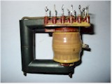
In such transformers the primary and the secondary coils are separated, so you can remove the bolts, separate carefully the two part of the ferrite and throw away the primary. Only the secondary and the ferrite are useful for our purpose.
![]()
Transformer secondary and ferrite parts
![]()
Detail of the high voltage coil
Now you can make your own primary. You can use for instance standard loudspeakers flexible copper wires of around 1mm2 section. The number of turns depends on the power supply you have and the power trans you may use. For a 30V maximum power supply voltage I have used 28 turns for the primary.
![]()
Close-up of the primary (28 turns of flexible copper wire)
When finished your transformer should look like this
![]()
The whole High Voltage High Frequency transformer
3 - The optional rectifier
If you want to use your transformer to produce continuous positive or negative voltage you may use the current high voltage diode model TV 18 or TV 20 (available from the DIEMEN company).
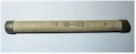
High voltage diode Ref: TV 18
If the voltage obtained is not sufficient or if you want to control more easely the maximum current that the power supply will deliver after rectification and filtering you may use the following system.

A simple reversible doubler
The maximum current is limited very simply by the use of a small capacitor value (in the pF range). These capacities that should support several kV are not so easy to find, but you may encounter some in very old TV sets. If you are not able to find some of them you may use the high voltage capacitors that are use in parallel with a high resistor value (usually 10 MOhms) to evacuate electrostatic charges between the primary and secondary of all modern switch mode power supplies. Note that the standard value of such capacitors are around 3nF and 3 to 4 kV (you should use at least two of them in serie). You should imperatively use the 10 MOhms resistor in serie with the capacitors to limit the final current if you want to put your finger there (but no arm if you don't, only a small shock). you can also try to make your own capacitor (two metallic plates and a plastic material in the midle). The capacitor's value is given by C = epsilon*S/d, where S is the surface of the electrode and d the distance (do not use a two thin plastic insulator if you don't want to make a hole in it through breakdown).
Note that the preceding solution is not absolutely necessary (but more versatile) and a single diode without nothing else will also do in many cases.
Do never use filtering capacitors between the high voltage and earth, because they are not only unnecessary (the electrode intrinsic capacity is enough to realise a perfect filtering at the high frequencies we are going to work, but they can be dangerous for you or your family (even if the power supply is off they will keep a charge).
4 - The power amplify
A very simple amplify can be built with very common elements.

A very simple power supply
The condenser value C depends on the frequency used (i.e. the resonance frequency of the transformer assembly) and should be on the nF range. Note that it is easier to use a low frequency generator to produce the square wave signal.
If you use the very common TIP 3055 and complementary TIP 2955 series you will have a pretty poor efficiency and you should use a quite large cooling in this case. It is a lot better to use faster transistors (and best Darlington assemblies) such as the BDX 53, BDX 54 pair (the ones I did use in the present case).

The power stage

The whole power supply in action in a high frequency point-to-nothing glow
5 - Advanced power supplies
If you need a higher power you may use 2SB 827 combined with 2SC 2581 (or many others) and BD 243,244 as drivers (for the Darlington assemblies), with these transistors I was able to reach H.V. power supplies of more than 50 Watts with a global efficiency of around 60%.
If you are a good technician you can realise a complete adjustable and regulated power supply with an adjustable current protection in using the following schematic:

Complete power supply (schematics)
Many specialized circuits can be used but the simplest is uC 723 combined with NE 555 (for the pulse generation). But many usual circuits used in P.W.M or S.O.P.S power supplies can also be used.